In previous posts, I described the process I went through to design and fabricate a circuit designed to safely apply 1mA of current to any load (including potentially a human). Up to this point, things had gone well. The TSC888 amplifier intended to measure the actual current flowing turned out to be a little small for hand-soldering, but my practiced and patient hands managed it okay. I wouldn’t recommend it to someone who is just starting out with surface mount components though.
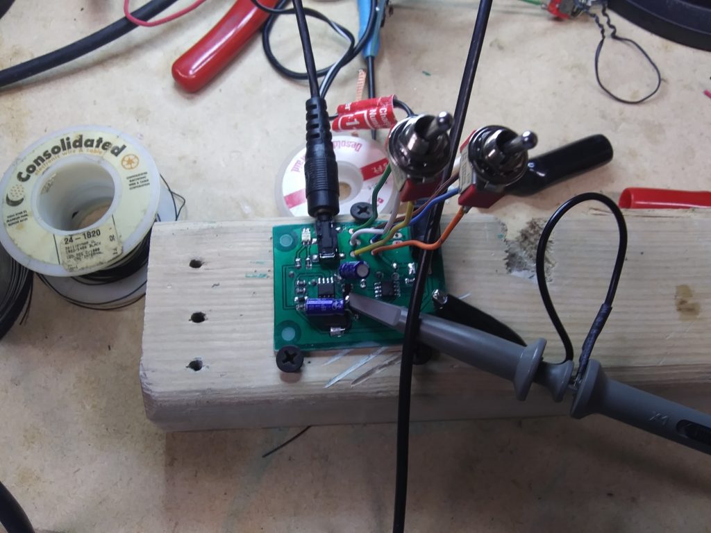
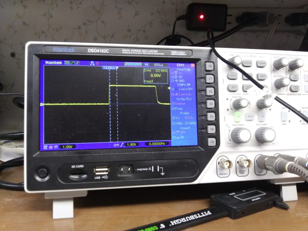
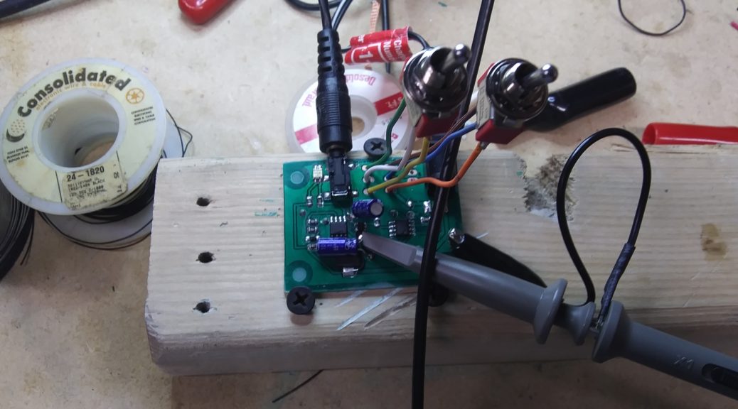
With the board built, I plugged in a 9V wall-wart transformer, connected a 1K resistor to substitute as a human, and switched it on. The LED blinked, then turned off. A little probing revealed that the fuse had been tripped. connecting my oscilloscope to a few test points and cycling the power switch revealed that the crowbar was working beautifully except for the fact that it was tripping due to power on transients. In an effort to continue evaluating the rest of the circuit, I added 1uf capacitors to the output of the TSC888 and to the input pin on the SCR. They are the blue cans visible in the picture below.

With the capacitors in place, the low setting seemed to work well. I measured 10mV across the 10ohm sense resistor, so the current source was working as designed. I switched the board to the 2mA setting, and so far so good. To test the ability of the regulator to handle extreme cases, I shorted the output leads together, and the low-current error light turned on. Weird… With the leads shorted, the current should be the same or higher than if the leads were disconnected. After a little fumbling and scratching my head, I realized what I had done wrong.
Consistent with most of the application notes and examples in the datasheet, I tied the power supply pin of the TSC888 to the output of the current regulator. This works fine when the load resistance (your body resistance) is relatively high, but when the resistance is low, the output voltage from the regulator drops very low to keep the current constant, and the TSC888 starts to behave erratically. It quits working all together if the connection is shorted because there is no power to drive its amplifiers, and that’s exactly when I want it to work the most. I had to pull off the chip, cut a trace, and tie the power supply pin (pin 5) to the input supply voltage (Vcc). A perfect example of why chip-quick is helpful… I know of no other way to reliably remove a surface mount component without destroying it (and often the board traces) in the process.
The output regulator worked perfectly everywhere from short-circuit to 10K ohms. If I didn’t care about monitoring or safety features, I’d be good to go. However, as I turned up the resistance, there came a point where the output of the TSC888 would drop out. Current would still be flowing, but the indication output would be 0V. I again connected my scope and dug in. Apparently the TSC888 is cutting of after a brief period. It’s unexplainable behavior. It could be because I damaged the IC by getting it too hot while soldering-removing-resoldering it, but if that’s the case, I should probably find something less sensitive. Otherwise, there is some “feature” I didn’t account for, and that part isn’t suited for my application in the first place.

So. To summarize… After all that work, I have to go back and redesign. The core building blocks all work, but there are definitely things to change:
- Add a diode in line with the battery terminal and power jack to prevent current backflow if someone connects external power while a battery is installed.
- Add filter capacitors to the crowbar signal to suppress transients that erroneously trigger a shutdown.
- Move the 10ohm current sense resistor to the load low-side and build my own op-amp detector to sense current flow instead of the TSC888. If I use another LM358, I can use the remaining op-amp to drive an indicator for whether 1mA or 2mA is flowing.
More to follow. I’ll redesign the circuit, build another board, and come back when I have something to report.

3 thoughts on “TDCS Controller Step 3 – Testing the Design”