An unfortunate outcome of many first attempts is the learning that goes along with failure. My initial design for a TDCS controller had some weaknesses (okay… outright failures). At first, I attempted to fix them on-board by cutting traces and soldering wires to re-route power, or by dead-bugging extra components onto it. However, you can only do so much without having to shift gears and start over. This post is all about the redesign.
The driving force behind the re-design was my inability to make the TSC888 current sensing amplifier work like I wanted. However, I can accomplish the same thing with a simple op-amp. In fact, the LM358 that I used as a voltage comparator can work pretty well, and I have a few extras of those around. The trick with using this kind of set-up is to either reference the current sense voltage to ground, or to build up a differential amplifier. The simplest method I could think of was to put the current sense resistor in the circuit after the load and make it the last component the current flows through on its way towards ground.
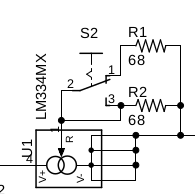
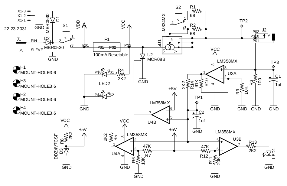
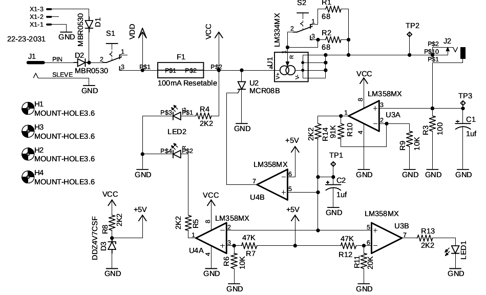
The basic current regulator is unchanged. It worked so well, I can’t come up with a reason to change it. With R2 at 68ohms, the regulator (U1) is hard-wired to produce 1mA. When S2 connects iwth R1, the effective feedback resistance generated by connecting R1 and R2 in parallel is 34ohms and results in a 2mA current.
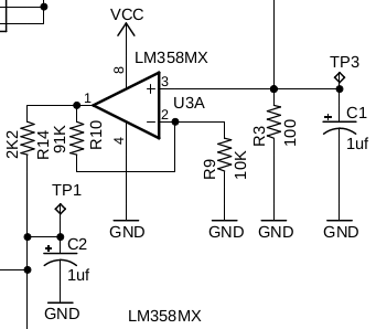
The nature of the LM358 calls for another change. It can have an offset voltage between inputs of several milivolts. With a 10ohm sense resistor like I had in the previous design, each milivolt of offset represents a 10% error at 1mA of current. However, increasing the sense resistor to 100ohms increases the sense voltage by a factor of 10, so a 1mV offset would only represent a 1% error. That’s good enough for me. Adding an extra 100ohms of resistance into the circuit shouldn’t really be an issue for my application.
With a 100ohm sense resistor (R3), I need a gain of 10 to produce 1V output per miliamp. Configuring an LM358 (U3A) for a gain very near 10 with a 91K (R10) and 10K (R9) resistors will replace the TSC888, and do so in a package that is easier to solder. I also added a 1uf capacitor (C1) to the output lead to absorb any transients that might inadvertently trigger the crowbar. I also added a 2.2K output resistor (R14) feeding another 1uf capacitor (C2). The resistor capacitor combination gives a 2.2ms time constant, so it will take about 10ms (5 RC time-constants) to react to changes in the output. This will help to further damp out any transients, but do so quick enough that a failure that result in a relatively high current won’t injure anyone.
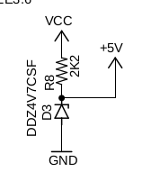
In order to determine if the output current is above 5mA, I can use an op-amp to compare the output of U3A with a 5V reference. However, that means I need a stable reference voltage. Since the supply voltage can vary from about 9V to 24V, I can’t use it directly. I could use a regulator like an LM7805, but there will be very little current drawn from that source so that would be overkill. Instead, I used a simple 2.2K resistor (R8) and 4.8V zener diode (D3) to derive the reference. The 4.8V zener blocks current until the voltage across it reaches the zener voltage (4.8V), at which point it lets current flow. R8 limits the current that can flow through the diode so it doesn’t melt once it starts conducting. I originally wanted a 5V reference, but the 4.8V zener was substantially cheaper than the 5V option and was close enough to meet my needs.
As before, I used an LM358MX op-amp for the voltage comparator. Each device comes with two op-amps in the package, including the one I used for the current sense amplifier. Ultimately, I need just one more amplifier to sense an over-current condition and trigger the crowbar, but I would also like some status indicators. Since the LM358MX is relatively inexpensive (and I have several extra available) I decided to add another one to the circuit.
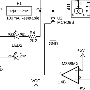
The crowbar driver (U4B) is very simple. The inverting input (pin 6) is tied to the 5V reference and the current sense output is tied to the non-inverting input (pin 5). When pin 5 is less than pin six, the output on pin 7 stays low (ground). However, if the output from the current sense circuit exceeds the reference voltage (approximately 4.8mA), the output on pin 7 rises to the supply voltage and triggers the SCR (U2). U2 then latches on and shunts the supply to ground. Once that happens, the fuse (F1) opens up and cuts off power to the whole circuit.
For convenience, I want two indicators: one to show when the 2mA setting has been selected, and one to show when the circuit can’t supply at least 1mA. The circuit for status indicators (LEDs) is similar to the crowbar driver, but I use a voltage divider (two resistors) off of the 5V reference to set the threshold voltage. I could have gotten rid of the indicator LEDs, and used one amplifier to run both the crow-bar and for current sensing, but they are cheap and easy to work with, so I opted to add another chip. The voltage divider on U3B set by R11 and R12 set a 1.4V reference on pin 6. If the output of the current sense circuit is above 1.4V (1.4mA output), pin 7 goes high and LED1 turns on. The divider on pin3 of U4A sets a 0.84V refrence. If the current sense voltage drops below 0.84V because the load resistance is too high (like when it’s disconnected) or because the battery has dropped too low, pin 1 goes high and turns on the red LED in LED2 (not shown). R5 and R13 limit the current through the LEDs to keep them from burning out.

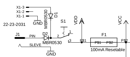
The final change I made from the previous attempt was to add diodes in line with the battery and power jack. If you’re only going to ever run this thing off of one or the other power source, there isn’t a need for the diodes, but if you happen to have a 9V battery plugged in and you connect a 12V power supply, you’ll end up with current flowing from the power supply into the battery. That can result in some nasty stuff. The opposite condition can occur if the battery voltage is higher than the power supply voltage. Two cheap diodes (D1 and D2) are all it takes to prevent that possible outcome.
So, putting it all together, here’s the end result:
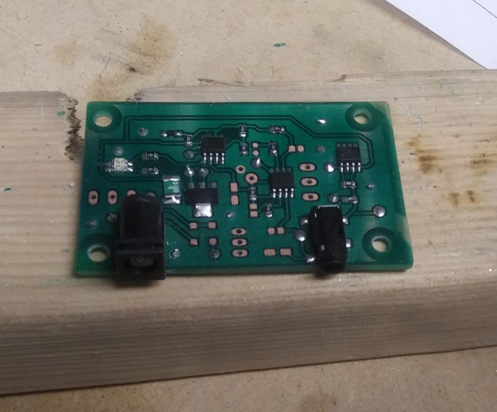
With the new design comes a new board layout (slightly larger, but easier to fabricate at home). The mask sheet containing the photomasks for both the photoresist and the solder mask can be downloaded here. The capacitors are Panasonic outline B, diodes are SOD-123 packaged, resistors are 0804 size, LED1 is 0804 and LED2 is a custom two-color LED footprint. The ICs are all SO8 packaged. The process I use for fabricating boards is described here if you want to try making one for yourself. The .brd and .sch files for Eagle Cad can be downloaded here.
I had to order a few extra parts with the redesign, and am waiting for them to arrive. Once they do, I’ll test the resulting circuit and post the results. Until then, if you make improvements or just decide to build your own, I’d love to hear about it. Leave me a comment below.
Looks good. Does it work yet? The last one I built burnt two holes in my forehead so this idea on current safe feature makes sense to me. I am building an EEG from the ground up this time. When this one works, let me know and I will advertise and sell them for you for free on my site. But I will make sure they work first. Keep up the great work! I wanted to do what you are doing but had to refocus my time to other things, so I support you where I can.
Yep. Works exactly as intended, but I might end up trying another electrode design… The copper reacts under current flow, but that’s not a surprise. I’ll probably shift to stainless steel mesh, but what I have now works well enough.
I’m not really interested in selling them. If I try to make it a commercial venture, it’ll take all the fun out of it. Anyone who wants to build one is welcome to use the design though.
I built two of them in case I burned one up in testing, but other than putting them in an enclosure, I don’t really intend to build more.
I do have a few tweaks I’d make if I were going to build up another version though. Right now, the power indicator and continuity (low current) indicator share a single two-color LED, and the 2mA indicator is on a second one. That’s a result of the iterations in design, but it would make more sense to have the two current flow indicators on the two-color LED, and put the power indicator on the separate led.
Same thing applies to the configuration of the op-amps – in a redesign, I’d use one chip to do the current sense and trip the crowbar circuit, and the other for running the indicator LEDs. That way, if someone wanted to save a few cents or use a panel mount voltmeter for indication they could omit the second chip and associated hardware.
Another thing I’d probably do is make it explicit that you can replace the current selector switch with a 1K pot to make the current adjustable between 1 and 2 mA. In that case, I might also replace the feedback resistors to widen the range from 0.5 to 2mA.
The last thing I might do is design a board layout for through-hole components for people who aren’t comfortable working with surface mount components. I’ve got 20+ years working with electronic components, so surface mount doesn’t bother me. That’s not universal.
Where would one find the LM334? I mean, if I wanted to reuse parts. With magnifying glass in hand, I have scoured hundreds of boards and have never seen one LM334 chip.
It’s most likely going to be paired up with a photo resistor or thermistor. A standard application for the LM334 is to provide a constant bias current through a variable resistance element so the resistance can be determined very simply from a voltage measurement. You might find one in a DVM for example.
I used to fix electronics for a living, and I don’t remember ever coming across one in common consumer electronics. For the time and effort it would take, I’d just order one new from Digikey, Mauser, or the like.