NOTE: This was an initial design, that evolved as I built and tested it. For the final design, complete with a description of each major component, see this post.
The fundamental building block for any TDCS controller is a current source capable of supplying between one and two milliamps of current through the human body. This can be a bit of a challenge because the resistance of the body varies with electrode placement, skin resistance (which can vary from one second to the next), body composition, and a bunch of other factors. The trick is to build a regulated current source capable of automatically adjusting the output voltage to get the desired current even with this rapid and unpredictable change in the person being exposed.
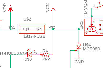
Digging through a pile of data sheets, I found a perfect solution already packaged and ready for integration. The LM334 current regulated source can be programmed to provide a constant current ranging from microamps to ten milliamps. All it takes it is a simple resistor to set the current. Two small and cheap parts are all that’s required for the basic circuit.
We’re I comfortable that nothing would ever go wrong, and didn’t want any feedback about what the thing is doing, that would be it. I could build one on a dime, and do it for just a few dollars. However, I’ve spent way too much time fixing electronics and have seen too many cases where the primary failure was a shorted out semiconductor to trust a piece of silicon to not short out. In fact, I made a good living in college taking advantage of that particular failure mode. If the regulator failed, there would be nothing to prevent a comparatively high current from flowing through my brain and doing significant damage. Clearly this thing needs a few more features.
First, I like the idea of being able to select a lower current setting. Most of the research I’ve seen uses either one or two milliamps, and I’d like to be able to use those two settings at least. I could pretty easily build in an adjustable resistor, but they are much more expensive than simple resistors, and I’ve not seen anything showing an advantage to being able to finely tune the output. Instead, I built in a switch and an extra resistor.
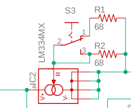
Rather than switch R1 and R2 in and out of the circuit completely and deal with the undefined state that happens during the switch transition, I hard wired R2 into the circuit and selected it to produce a 1mA output. When the switch is closed, R1 is added in parallel with R2, cutting the effective resistance in half, and subsequently doubling the output current to 2mA. If the regulator doesn’t fail, the current won’t ever be anything other than 1mA or 2mA. A simple flip of a switch will seamlessly change the output between only these two values.
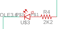
With that aspect of the design complete, the next step is to provide an indicator that the thing is on. It’s a simple matter of adding a resistor and an LED on the power line. The maximum voltage the regulator can handle is 40V, so I selected a resistor value that would limit the current to about 15mA or less through the LED at that input voltage. Lower voltages will still light the indicator, but it just won’t be as bright. For my purposes, that’s okay.
The last three things I want in the design can be incorporated with a single basic feature. I’d like some indication when current isn’t flowing, be able to monitor exactly how much current is actually flowing, and a safety feature to shut the thing down if the regulator fails for any reason. To do any and all of these things, I need to be able to monitor exactly how much current is actually flowing through the body.
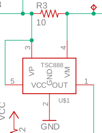
It can be a little difficult to measure low currents without disturbing the system. Initially, I believed the pile of data sheets had a ready made answer. The TSC888CILT is designed to measure the voltage across a shunt resistor and provide a gain factor to make measurements easy. Combined with a 10 ohm precision resistor, the chip puts out a 1V/mA signal.
With a signal to monitor the output current I can do several things. First, and most importantly, I want the device to shut off completely if something goes wrong and current rises above a safety threshold. If the output current exceeds 5mA something has gone wrong, and 5mA is well below the damage threshold for tissue. The simple answer for circuit protection would be to put a fuse in the line. However, mA-range fuses are hard to find, are bulky, and may not react fast enough to satisfy me. On top of that, I’m not particularly keen on replacing fuses if I happen to accidentally short something out while testing. This is where the current sense signal comes in handy.
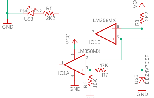
It’s pretty easy to set up an op-amp as a voltage comparator and use it to trigger a “crowbar” if the output current exceeds a set value. The idea of a crowbar is that it’s like dropping a metal crowbar across two electrical terminals to blow a fuse or trip a circuit breaker. With the 1V/mA sensing gain and a 5mA threshold current, all that is required is a 5V reference voltage on the inverting input and the current sense signal on the non-inverting input. For the reference voltage I used a simple zener diode and resistor. I also used a 4.8V zener because it was cheaper than the 5V ones available at the time, and because 4.8 mA is still high enough that I want to shut things down if the current goes that high.
The output of the comparator then needs to drive the crowbar. I added a resetable fuse just after the power switch. This fuse is guaranteed to hold 100mA (plenty to run everything) and trigger before something like 250mA. The MCR08B Thyristor can handle 800mA, so it will happily load the fuse when triggered. The output of the voltage comparator will trigger U4, which will turn on and stay conducting until power is removed. When the SCR turns on, the resetable fuse opens up and cuts power until power is totally disconnected and the fuse cools. Theoretically, none of this part of the circuit should ever actually function, but I’m happier knowing it’s there. If the current regulator fails, the crowbar will shut things down without putting anyone in danger.
Because the chip I used for the crowbar trigger has two op-amps, I have one to spare that I can use as a fault detector. If the output current falls bellow 1mA, either the electrodes are disconnected, the connections are poor (i.e. they are too dry), the battery is low, or something else is wrong. R6 and R7 form a voltage divider off of the 4.8v reference used for the crowbar, and sets an 840mV reference for the voltage comparator. Any time the output current falls below 0.84mA, the output of the op-amp goes high and turns the red LED on.
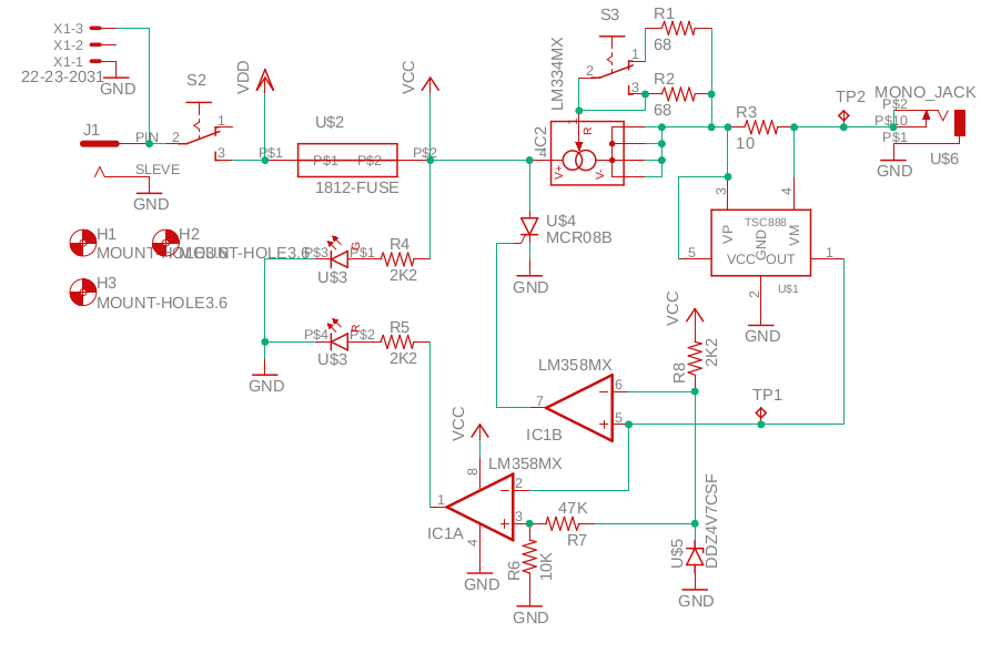
The last parts to add are jacks for power and to connect the output leads. I used a simple mono-headphone jack for the output, and a 2.1mm barrel jack for the input power. I also added a connector and a diode to make it so I can plug in a 9V battery instead of a wall-wart transformer. When connected to a human, you should run this thing on a battery all the time to make sure you don’t encounter any ground-loop issues. At a minimum, make sure that the output of your power supply is floating with respect to earth ground (if you don’t know what that means, use a battery). There are good reasons hospitals have outlets with the neutral floating with respect to the ground pin. Finally, I added some mounting holes to the diagram so they show up on the board.
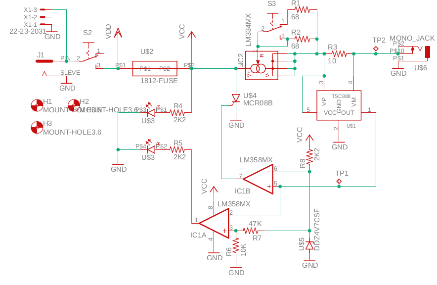
All combined, the circuit looks like this:
I laid the board out in such a way that I can reliably make my own by using 15mil clearances between traces, and 20mil minimum traces. I could have made it much smaller if I were going to farm this board out to a fab house by putting components on both sides of the board, using small vias, and finer traces. However, I like rolling my own boards, so traces are pretty thick, all the components are on the top-side, and vias are large enough I can drill them, stick a wire through it, and solder it to both sides. The final board is just under 2″ on the long side.
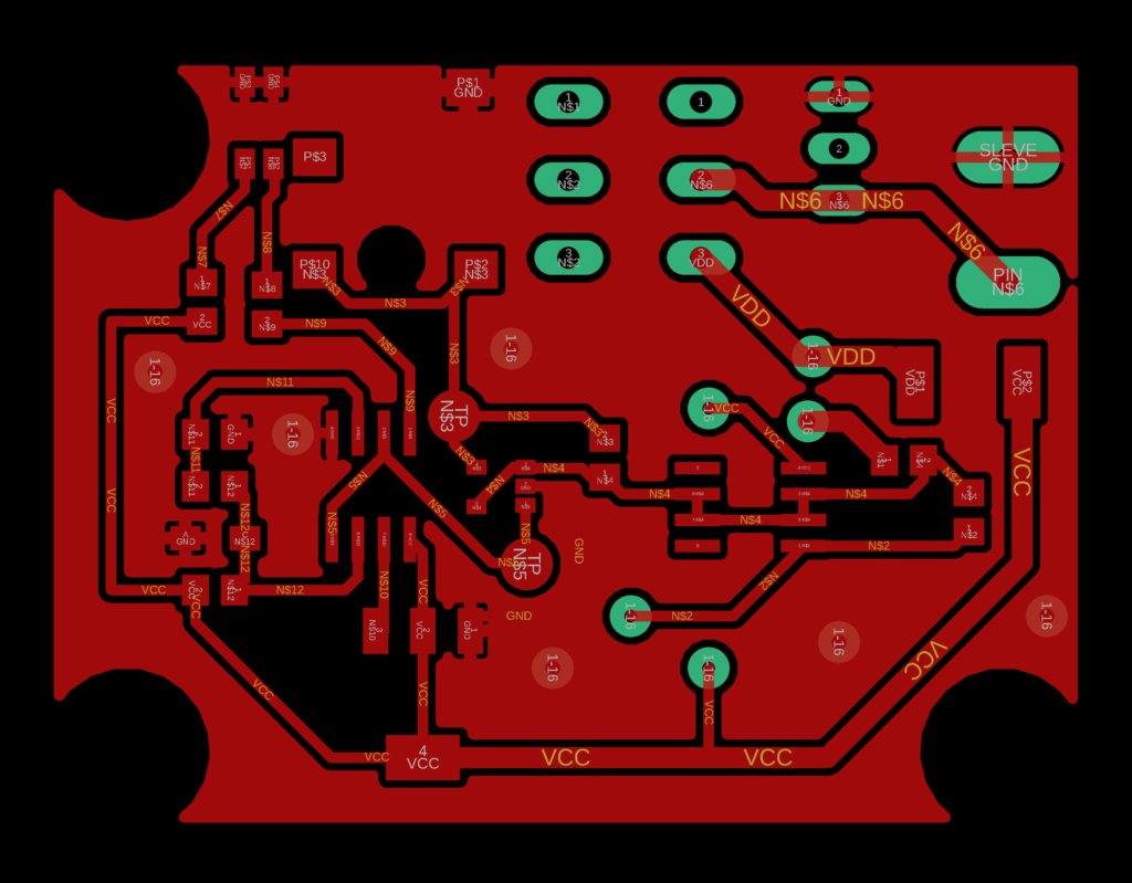
Now, on to making the board.
One thought on “TDCS Controller Step 1 – Design”