In the ham radio community, homebrewing is a term used to describe making your own radio gear. For most hams, this doesn’t go much beyond building and tuning an antenna out of copper pipe or wire, but I’m not really your average ham. For one, I am almost never on the air. That said, as I’ve spent more time recently reconnecting with my roots as an Electrical Engineer, I’ve opted to use my license as an excuse to play around with ideas.
In the process of building my last project (the sunrise light https://diligent5.org/?p=1849) I bought an Arduino Uno to mess around with and compare with the capabilities of the Raspberry Pi I already had. In looking at the availability of A/D inputs and various forms of serial I/O on the Uno, I had a flash of genious (or insanity) where I thought it might make a decent controller for an antenna analyzer driven by an AD9851 direct digital synthesizer (DDS). So, what, you might ask (especially given the nature of the few people who actually read any of this blog), is an antenna analyzer?
Antennas are “resonant structures” which roughly means they are the electrical equivalent of an organ pipe or guitar string. Based on their construction, they will resonate at specific frequencies. The frequencies where they resonate are the frequencies where they work well. Trying to use an antenna that isn’t tuned to the frequency you are trying to transmit on will result in most of the energy going the wrong place (back into the transmitter instead of going out over the air for someone else to listen to), and can actually destroy your equipment. If you are going to build an antenna, you need to be able to tune it the same way you tune an organ pipe or guitar string, and in order to tune it you need a device to send tones into the antenna and measure how the antenna reacts to them. That is what an antenna analyzer does.
Analyzers are commercially available for both ham and commercial radio bands, and range from a few hundred dollars to a whole lot more. I’ve been eyeballing them for a long time so I can start building antennas, but I’ve never been able to talk myself into spending the money on one. But… if it’s a project, I build it a few dollars at a time and get the benefit of feeding my inner geek. Never mind how much it actually costs (especially if you factor in time).
Analyzers are fundamentally pretty simple. First, you generate a signal at the frequency you want to test, then use it to drive a bridge circuit. The rest of the analyzer is all about digitally measuring voltages across the bridge and converting those measurements into the parameters I’m interested in. As luck would have it, I’d been scanning various products advertised for the “maker” community (people who build stuff using Arduinos and such) and had seen an ad for modules based on Analog Devices AD9851. This chip uses a fast digital-to-analog (D/A) converter to generate a high-quality signal output that is digitally controllable from zero up through roughly 75 MHz (million cycles per second). This chip, combined with some filtering and amplification would make a perfect source to build my analyzer on.
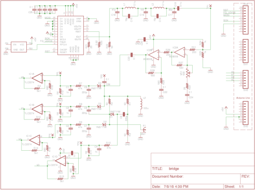
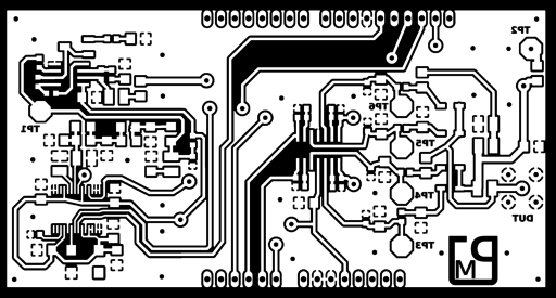
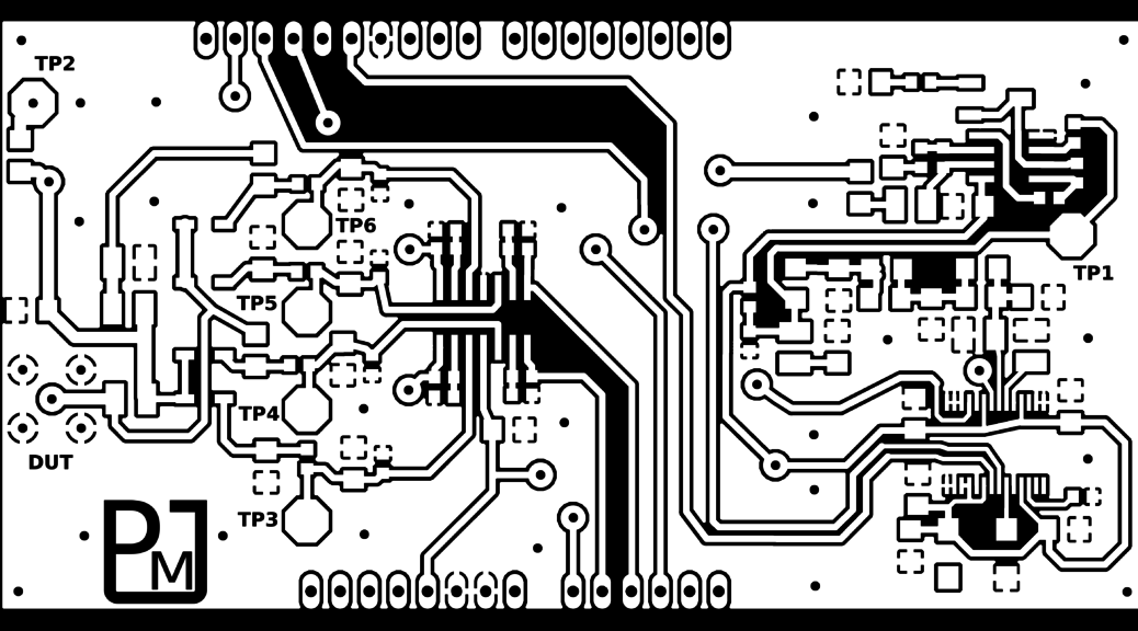
Rather than buy an already complete module and have to figure out how to mount it, I opted to start from scratch and build a board that integrated the AD9851, would plug directly into an Arduino Uno, and contained everything needed to take the measurements (except for the user interface). I’d use the arduino to program the AD9851, digitize the measurements, do the calculations, manage communications via USB port to a host computer, and run a display and buttons. I grabbed a bunch of datasheets, opened eagle cad, and laid out my schematic and board.
Like most projects, it wasn’t nearly as straight forward as it seemed. I ran into a host of hiccups along the way, but over the next few posts, I’ll try to explain how it works and the gotchas I ran into.


